OpenWheel
An open-source motorised filter wheel — from a stepper twitching on a breadboard to firmware, an ASCOM driver and a printable DIY release, built together with AI.
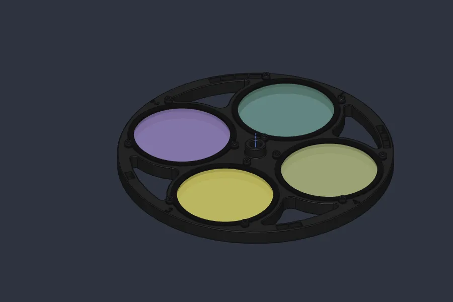
OpenWheel is the filter wheel on my imaging rig: four 2” filters, a stepper motor, a Hall sensor reading magnets in the rim, and a small STM32 board on USB. N.I.N.A. sees it as a normal ASCOM filter wheel. It took two years to get here. For most of that time it was a hobby project that grew slowly. In the last weeks it changed faster than in all the months before, because I stopped writing everything myself and started working with an AI.
This is the story of how it got here, including the parts that didn’t work.
2024: a motor and a magnet
It started in November 2024 with two Arduino sketches on an STM32: MoveBackAndForth and Simple.
They did nothing more than spin a stepper through a TMC2209 driver in both directions. The
mechanical side lived in Solid Edge, together with the first KiCad board, whose parts I exported to
check that everything fit.
The idea that is still in the wheel today came early: every filter slot is marked by a group of magnets of a different length. As the wheel turns, the Hall sensor sees a pulse whose length tells which slot is passing. There’s no encoder and no index hole, just a few cheap magnets and some timing.
How does a filter wheel know where it is?
Every motorised filter wheel has to answer one question before each exposure: is the right filter really in front of the sensor? There are four common answers.
| Approach | How it works | Who uses it |
|---|---|---|
| Home sensor + step counting | One sensor finds a single home mark; every other slot is “N motor steps from home”. | Most DIY wheels; many observatory instruments too, where the sensors only verify the end positions |
| Optical sensor + holes | An infrared light barrier looks through positioning holes or slots in the wheel. | ZWO EFW (manual), older instruments with opto-couplers |
| Hall sensor + a magnet at each slot | A magnet in the wheel marks each position; the sensor finds the magnet’s centre or edge. | Player One Phoenix (product page), Gemini’s NIFS spectrograph |
| Binary-coded magnets + several sensors | Each slot carries its own pattern of magnets, read by three sensors at once: three bits identify seven filters. | Research instruments such as the Omega2000 IR camera |
A 2010 paper from the Bulgarian Academy of Sciences (Atanassov & Bankov) sums the trend up: opto-couplers were used to mark positions in the past, and Hall sensors with magnets have taken over. Player One makes the same argument for the Phoenix. With an infrared sensor, the accuracy depends on the size of the hole, so they put a magnet on the filter plate instead.
What OpenWheel does
OpenWheel takes the magnet idea one step further, with one Hall sensor and a magnet group at every slot. The groups have 4, 3, 2 and 1 magnets, so each slot sends a pulse of its own length. That makes the position absolute: every slot identifies itself.
The magnets are ordinary 6 × 3 mm cylinders, the same size the 3D-printer community uses in countless builds, so they’re cheap and easy to get. Nothing depends on that exact size, though. Calibration measures each group’s pulse, so other sizes or shapes work too: smaller cylinders, blocks, or fewer magnets per group. The one rule is that the groups must stay clearly different in length, and a change of count or spacing should be checked against the firmware’s pulse matching (#10 covers a variant with smaller magnets).
- The firmware measures the pulses in motor steps, not in time, so speed doesn’t matter. During calibration it turns the wheel, averages the pulses, counts the slots on its own and picks the shortest pulse (the single magnet) as home.
- A move ends on the magnets, not on a step count. While the wheel turns, every pulse is matched to a slot. The wheel stops when the target’s own group goes by, plus a small calibrated offset from that magnet edge. Steps only have to be right over that last short distance, never over a full lap.
Why that matters for this wheel in particular:
- Slip doesn’t accumulate. OpenWheel is driven by friction (a silicone tube on the motor shaft pressing on the rim), and friction drives slip. With step counting, every slip would shift all the following slots until the next homing. Here, the next magnet group puts the position right again.
- No homing after power-up, and nothing gets lost if someone turns the wheel by hand. The first group that passes the sensor tells the wheel where it is.
- Dust and light don’t matter. A magnetic field doesn’t care about dust in the chamber, and nothing in the light-tight chamber emits light.
- It notices when something is wrong. If no magnet pulse arrives within about 30 seconds, the wheel stops and reports error 6 (“Hall not seen”) instead of spinning forever.
- It’s cheap and forgiving to build. Ten 6 × 3 mm magnets and an A3144 sensor cost very little. The pockets don’t need to be placed to a hundredth of a millimetre, because calibration measures what’s really there. The same firmware works for 3 to 9 slots.
It has trade-offs too:
- It only turns one way. Going back one slot takes a full lap (about 4.6 s instead of 2.1 s).
- The magnets must all face the same way: the A3144 only switches on a south pole. A live sensor readout for checking that before gluing is coming in firmware 1.3.0.
- The walls between neighbouring magnets in the printed rim are only 0.47 mm thick.
- The sensor’s height against the magnets is still an open question for the first print.
2025: borrowing someone else’s protocol
To be useful at night, a filter wheel needs a driver that imaging software can talk to. Writing one was more than I wanted to take on, so the first firmware (January to March 2025) pretended to be a Xagyl wheel, a commercial filter wheel whose protocol existing drivers already understand. Later I added the protocol of the myFilterWheel DIY project as an option, with its own ASCOM driver and a small Python/Qt test GUI.
The board went through a second revision in autumn 2025. The firmware got calibration, EEPROM storage and button handling. It worked, more or less. But every feature was a compromise with a protocol designed for somebody else’s hardware.
Late 2025: the first AI helpers
In December 2025 the repository got its first copilot-instructions.md: notes for an AI coding
assistant explaining the magnet coding, the state machine and the configuration. Writing those
notes made me describe my own design properly for the first time.
In January 2026 came the biggest hardware step: migration from the STM32F103 “Blue Pill” to the STM32G0B1 with native USB. That meant a new pin map, USB CDC instead of a USB-serial chip, and the I2C EEPROM on new pins. The migration guide from that time is still in the private archive. It was also when Claude Code first appeared in the project folder.
October 2026: making it a real project
On 18 October 2026, in one long session with Claude, the project turned into something I could publish:
- A new name and its own protocol. “myFilterWheel” became OpenWheel. Protocol v2 keeps the
:NN#framing I was used to, but now every command gets an answer:OK#, a value, orERR,<code>#. On top of that come a status command, sticky error codes, and an identify command that lets the PC recognise the wheel on its own. - My own ASCOM driver. It finds the wheel by its USB ID, so there’s no COM port to choose. It stores filter names and focus offsets in the wheel, so they move with it to any PC. It is written so that a silent, unplugged or garbage-sending device never hangs N.I.N.A. It has 54 unit tests against simulated misbehaving devices and passes the official ConformU checker with no errors or warnings.
- A real USB ID. I applied to pid.codes for a product ID of its own instead of a borrowed test ID.
- A clean public repository on GitHub (GPL for the software, CERN-OHL-S for the hardware), with old experiments and third-party reference code moved to a private archive.
A confession about the schematic
Time to own up. My original schematic was quick and dirty: blocks copied and pasted from several older projects, stitched together until the board worked. Nets had no sensible names, leftovers from the donor projects stayed in, and there was no single place you could read it from.
And it had a real mistake: I ran the Hall sensor on 3 V instead of 5 V. The A3144 is specified for 4.5 to 24 V, so on 3 V it was outside its datasheet from day one. The wheel’s whole position sensing hung on a part running below its minimum supply. The fix is simple: the sensor now runs on 5 V. Its output is open-collector, so the microcontroller’s own pull-up keeps the signal at a 3.3 V-safe level.
So at the end of October the schematic was redrawn from scratch as functional blocks with named nets and a proper title block. The board revision added:
- USB ESD protection (USBLC6) and a shield RC network;
- 5 V supply sense on an ADC pin, so the wheel can report brown-outs;
- an RC filter on the Hall input and 47 µF of bulk capacitance on the motor supply;
- dimmer LEDs (5.1 kΩ instead of 510 Ω, dark enough for a night session);
- a cleaned-up PCB: redundant vias, clearance violations and dangling stubs removed.
Firmware 1.2.0 moved the clock to the crystal and added stall detection and the health readout (temperatures, supply voltages), which the driver shows in its setup dialog.
November 2026: the mechanics, rebuilt in SolidCraft
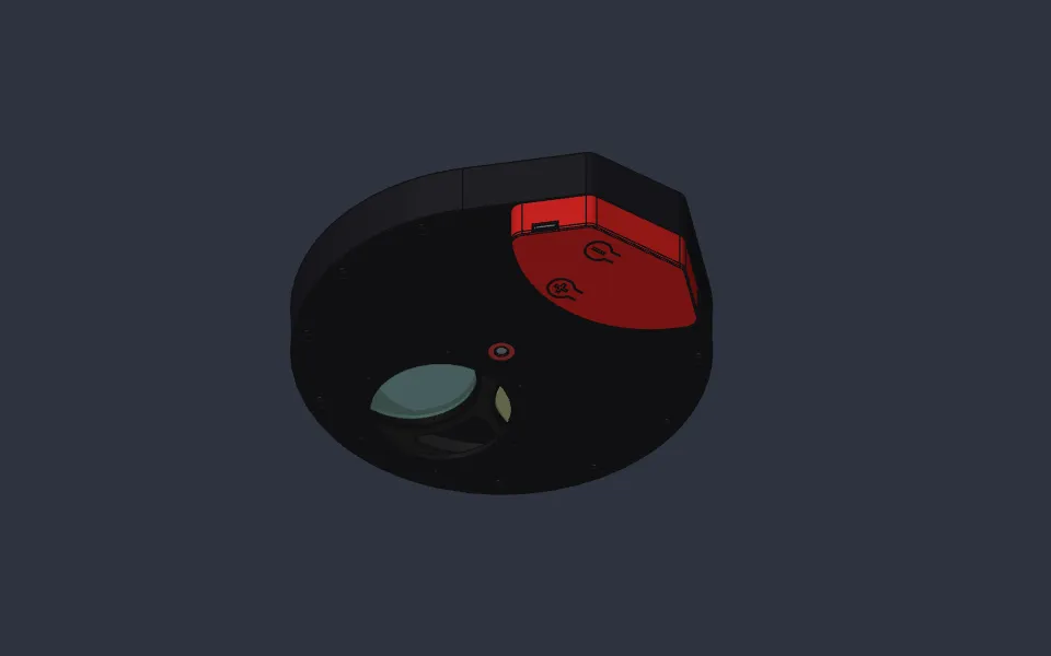
The electronics and software were in good shape, but the mechanics were still the old Solid Edge models: a shell with “horns” for an off-axis guider I no longer use, plates without exact tolerances, and no documentation anyone else could build from.
So in the first days of November I rebuilt the whole DIY release in SolidCraft, a parametric CAD program that Claude can operate directly. I described what I wanted and watched the model appear in the viewport. Claude ran the sketches, extrusions, measurements and section views and wrote down every decision. In four days I got:
- a shell without the horns, with exact plate recesses and channels for twelve standoffs;
- front and camera plates ready to order from JLCPCB as 3 mm black-anodised CNC aluminium, with M48 and M2.5 threads;
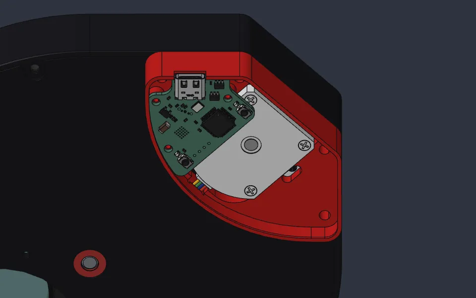
- a motor box with a clip-in lid: printed button pads on hinges, a USB-C opening across the seam, and every inner edge chamfered against elephant’s foot;
- the full linked assembly with bearings, shims, shaft and screws, checked for interference;
- DIY notes with a bill of materials and a build order, written as the model grew.
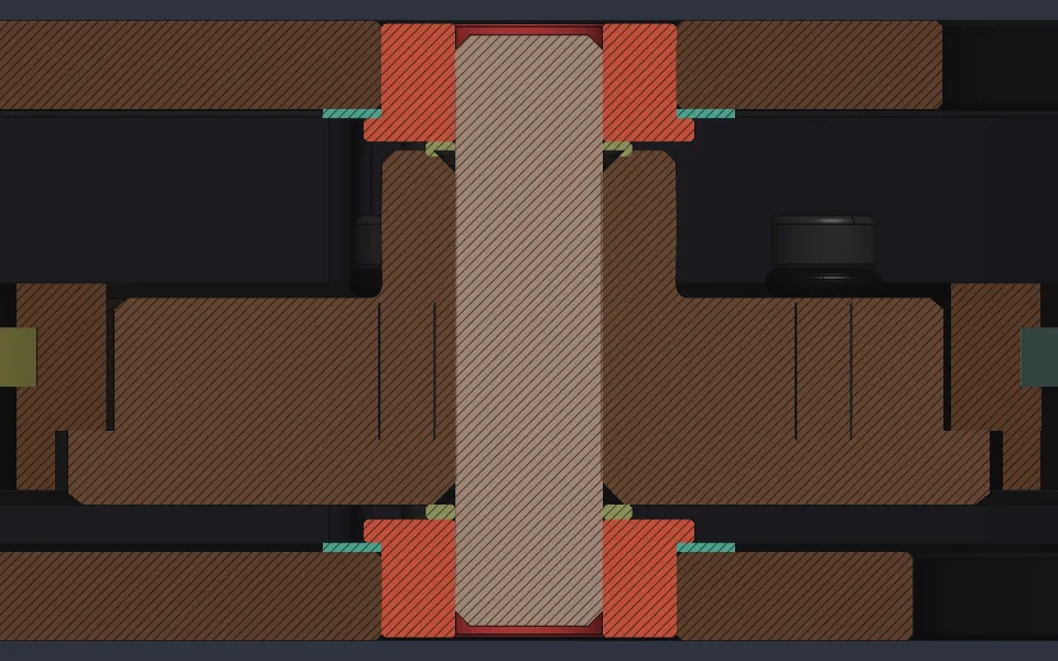
The section above is a good example of the work. The 21 mm stack has to lock the wheel with no axial play, and nothing may stick out of the outer faces, because the camera sits right against them. Getting there meant counting tenths of a millimetre: a 0.3 mm shim under each bearing flange, a 0.5 mm shim on the shaft, and a hub that is sanded from 12 to 11.8 mm.
What SolidCraft was like
I want to be honest about this part, because it was the most interesting and at times the most frustrating.
The good:
- Everything is parametric and scripted. When the motor box needed to be 4 mm lower, it was a parameter change, not an evening of redrawing.
- Claude can measure, cut sections and render views on its own. About fifty review renders came out of those four days, and I reviewed the design from pictures before anything was printed.
- Every printed part went through a gate before release: no feature warnings, and a closed mesh (0 open edges) in the exported 3MF, plus a printability check for overhangs, bridges and thin walls.
The not so good: SolidCraft (version 0.29) is young, and its geometry kernel has sharp corners. In those four days we logged 17 problems in issue #11, each with a workaround. Some examples:
- Two small chamfers that overlapped by 0.1 mm built without complaint, but the exported mesh had 61 holes in it.
- A plain cylinder cut silently corrupted the body: it lost over 1,000 mm³ of volume and grew a spike. The fix was to put all eight channels into one sketch and cut them in one go.
- Fillets fail next to the seam of a cylinder, and cuts fail across chamfered edges. The rule became: all cuts first, chamfers last.
- Modelled threads make it very slow, so all threads are cosmetic. A STEP import with open bodies stops the assembly from saving its model, so it rebuilt on every open until we replaced that import.
Four of these, the ones in SolidCraft itself rather than its geometry kernel, went upstream as bug reports. The rest are documented with their workarounds, so the next revision doesn’t hit them again.
How the AI actually helped
So did the AI build it? Much more of it than you might expect. Claude wasn’t writing code blind: the wheel was plugged into the same PC, so it had real feedback from real hardware.
- Talking to the wheel over the serial port was everyday work. Claude sent commands, read the replies and debugged from what the board actually answered, not from what the code was supposed to do.
- Flashing without touching anything. A “magic packet”, the
:31#command, reboots the wheel into its USB bootloader. Claude builds the firmware, checks that the port really is an OpenWheel, sends:31#, waits for the DFU device, uploads, and checks the new version once the wheel is back on USB. The whole build-flash-test loop runs without me pressing a button. - Hardware tests on the real board. The acceptance tests, the ASCOM driver checks and ConformU all ran against the actual wheel, not a simulator.
- Even N.I.N.A. is within reach. Controlling Windows and the imaging software itself is technically possible, so the last step of the chain could be automated too.
What stays with me are the hands and the decisions: printing, soldering, gluing magnets, assembling and judging the result on the real thing, and the design calls, from removing the horns to driving the wheel by friction through a silicone tube instead of a belt.
What changed was the speed and the discipline:
- The boring parts got done. Unit tests against broken devices, conformance runs, the pid.codes application, licences, a protocol reference that matches the firmware. I would have postponed all of that forever.
- Nothing is undocumented. Every session ends with notes: what was decided, what is still open, what to do next. The handoff file means I can pick the project up after a month without guessing where I was.
- Repeatable routines. The flashing loop above (
/flash-fw) and the hardware acceptance tests (/test-fw) are short skills Claude runs the same way every time. - CAD without the mouse. For the mechanical part this was new to me. I spent my time deciding and checking, not clicking.
It also made mistakes: wrong assumptions about parts I hadn’t described, and a pulley and idlers copied into the build order from a different project. They were caught because everything was written down and checked against the real thing.
What the wheel can do
Set-up and calibration
- Automatic calibration. One long press on CW, a button held at power-up, or a click in the driver. The wheel turns, measures every magnet group, averages the pulses and stores the result in its EEPROM.
- Detects the number of filters. It counts the slots by itself (3 to 9), so the same firmware fits different wheels.
- Finds home by itself. The shortest pulse (the single magnet) becomes home. There’s no separate home sensor and no homing run after power-up.
- Filter names and focus offsets live in the wheel, not on the PC. Move the wheel to another computer and N.I.N.A. can import them from there. They survive a recalibration.
Talking to the PC
- Found automatically. It has its own USB ID (pid.codes) and answers an identify command, so the driver finds it without you picking a COM port.
- Every command gets an answer (
OK#, a value orERR,<code>#), so a command can never be silently lost. - ASCOM driver (
IFilterWheelV3) that passes ConformU with no errors or warnings, with extra actions for Status, Home, Halt, Clear error and Calibrate. It never hangs the imaging software: every call has a time limit, a lost connection is retried in the background, and a move that never ends is halted. - Setup dialog (gear icon in N.I.N.A.) to edit filter names and offsets, watch the live status and health, and run calibration.
Housekeeping and safety
- Health readout: MCU temperature, supply voltages and motor-driver temperature, with warnings for low supply, driver overtemperature or reset, and a crystal that isn’t running. Warnings go to the driver log as they appear.
- Stall detection: a Test move measures the motor load and suggests a threshold, which is stored in the wheel (0 = off).
- Sticky error codes: “Hall not seen”, stalled motor, driver fault, EEPROM fault, move timeout. They’re shown on the LEDs for 10 s and kept until they’re cleared, so a fault in the middle of the night is still visible in the morning.
- Dimmable status LEDs, 0–100 % or off, for dark sites. One LED blinks while moving, the other blinks the slot number on arrival.
Hands-on
- Two buttons: a click moves to the next or previous slot, a double click homes, and a long press calibrates.
- Firmware updates over USB: hold CCW at power-up (it’s wired to BOOT0) or send
:31#to enter the bootloader. No programmer is needed. - Powered by USB alone (5 V behind a 0.5 A polyfuse). One cable carries both power and data.
Where the parts come from
You can build one without a workshop:
- PCB: made and assembled by JLCPCB from the KiCad files in the repo. The board arrives with its components already fitted; only the motor wires and the Hall sensor get soldered by hand.
- Front and camera plates: 3 mm aluminium, CNC-machined and black-anodised at JLCPCB from the STEP files, with the M48 and M2.5 threads ordered with them.
- Printed parts: the shell, wheel, motor box and lid, on any FDM printer in opaque black (the motor box can be any colour).
- Everything else from AliExpress: the NEMA11 pancake stepper, 6 × 3 mm magnets, A3144 Hall sensor, MF105ZZ bearings, shims, 5 mm shaft, M3 standoffs, screws and O-rings. All of it is standard hardware, and the parts list in the DIY notes gives sizes and quantities.
Where it stands
- Firmware 1.3.0 is coming, with a live Hall sensor readout, so builders can check the magnet polarity in the driver’s setup dialog before gluing.
- An INDI driver for Linux setups is in progress.
- Next up: the first print and fit of the new shell, motor box and plates, and the illustrated build manual.
The whole project — firmware, driver, KiCad, CAD and notes — is on GitHub.
In use on the rig as OpenWheel.